Building Three Rivers
January 2005
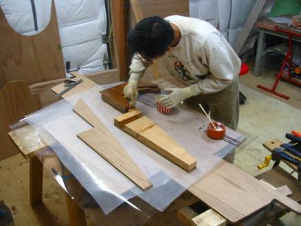
I am making slow but steady progress with my Chebacco, mainly building the major components first before I start on the hull which will take up most of the available work space. The following are a few photos on items that I’ve done differently.
Center Board: Instead of using lead, I’ve sandwiched the CB with 4 long pieces of ¼” mild steel. It should make the CB much stronger and hopefully will better withstand a lateral grounding. The total weight is about 60 lbs, a bit heavier than the standard construction.
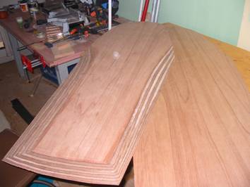
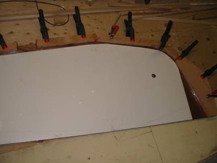
The glued up and shaped plywood CB:
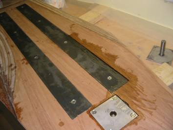
Center channels routed in for the two steel bars to lay
flush. One side of the bars is threaded to accept the through-bolts. Sitting at
the corner is the hinge assemly that will go on the CB trunk.
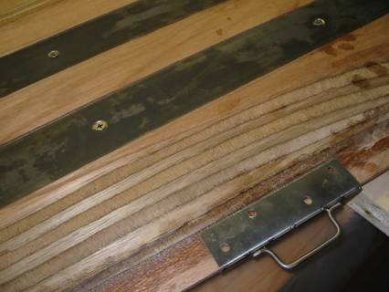
The CB sheet will go through this U-bracket. Since the bracket is gripping the thin edge of the CB, I made it 6” long with 4 through-bolts in order to spread out the load. I specified a small eyelet to tie the line, but the welding shop decided that it should be a larger hand-hold instead. Oh well.
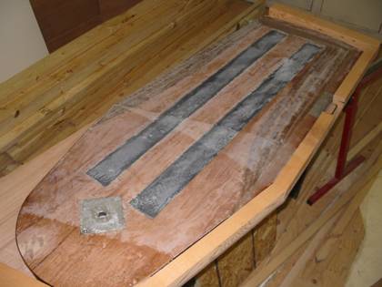
The CB glassed, dry fitting in the CB trunk.
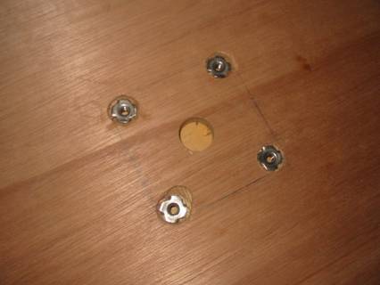
These S.S. T-nuts are ideal for holding the mounting plate on the trunk:
Gluing up the CB trunk; the white piece lining the inside
surface is counter-top laminate. This stuff is incredibly resistant to abrasion
– I run my sander with 60 grit paper on it for 2 minutes, with no visible wear
at all!
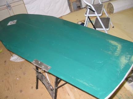
The completed CB with a couple of coats of Interlux paint. To protect againt wear & tear, I build up a ¼” finger of epoxy along the bottom edge. A half-oval bronze strip will be further added on, once I figure out where to get them.
Chebacco Raised Deck

Sometime ago I commissioned PB&F to modified the Chebacco, mainly to enlarge the cabin by lengthening and raising it, and to move the after-deck back by the same amount in order to keep the cockpit length. The Chebacco Raised Deck is the resulting design. I subsequently decided to stay with the existing plan, because I’ve already started on it and also I prefer the old look. However some design changes are excellent ideas which I’ve gone ahead and implemented on mine. I will cover some of them here.
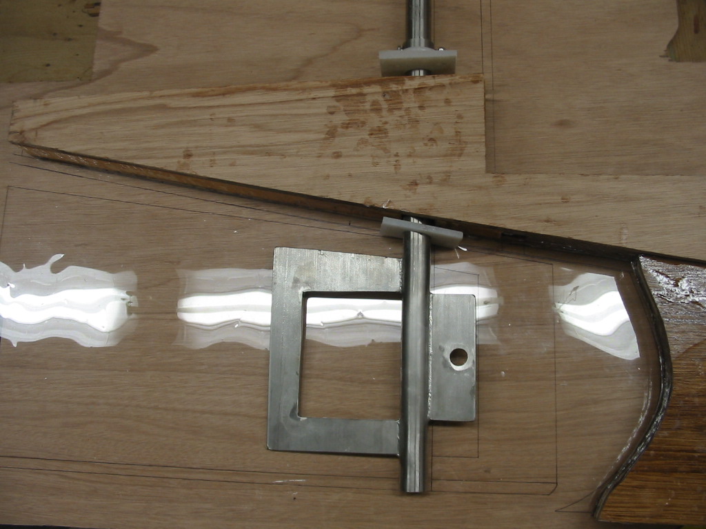
One of the biggest changes is the whole area near the transom. The rudder is now a balanced rudder with a tab forward of the rudder shaft, increasing the overall rudder area by about 25%. Due to the larger rudder and also the last bulkhead having moved aft, the keel skeg is no longer directly supporting the last bulkhead as in the original design. Hence there’s a fairly complex ‘backbone’ added to strengthen up the whole section:
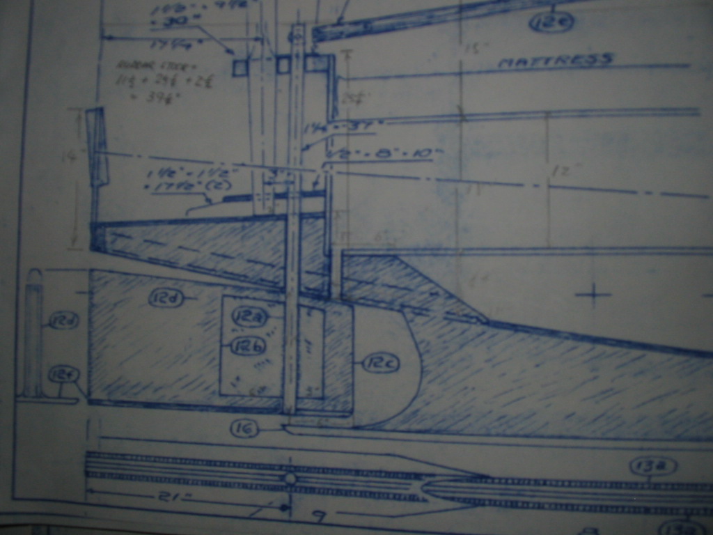
The transom backbone is a solid piece 2.5” thick, supporting the mizzen mast, rudder stock, and the slop well. The design calls for this to be one continuous piece as part of the keel. The rudder runs through the center of this piece. The small hole to the right of the ‘backbone’ is the drain. The cockpit is now a raised, self-draining cockpit.
I find it too cumbersome to have such a huge, complex keel, so I broke it down and built the transom backbone as a separate component, with a large part that goes below the bottom panel and will be solidly glued to the keel later:
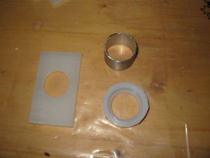
Bushings for the rudder, made from high density polyurothene (i.e. kitchen cutting board), and a stopper ring cut from 1/16” SS tube that fits the outer diameter of the rudder stock.
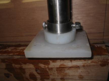
Another deviation from the original design: I am concerned
about mounting the rudder on a plate that protrudes a fairly long distance from
the keel. What if some 300 lb gorilla sits onto the rudder while the boat is on
a trailer? Instead of mounting the rudder off the keel, the transom backbone is
a much better alternative. It provides a strong, balanced position to hold the
stock with simply a stopper ring. The ring is glued to a PVC cap to provide a
larger surface area, which rides on a nylon bushing. The bottom bushing shown in
the picture is to be half-recessed and screwed onto the bottom panel, to protect
the rudder from going up and grinding onto that area.
That’s it for now. Time to get back to work!
Cheers.